Introduction
In a personal project, I wanted to add 2 new devices to an existing quadcopter. The quadcopter was equipped with a 6-channel receiver meaning I only had 1 spare channel to control the 2 devices:| CH 1 | : | Throttle |
| CH 2 | : | Rudder |
| CH 3 | : | Ailerons |
| CH 4 | : | Elevator |
| CH 5 | : | Flight mode |
| CH 6 | : | ??? |
EDIT: To make all mixing pre-calculations easier, do not hesitate to use my Mixing Calculator for R/C Transmitter (it’s an Excel Sheet!)
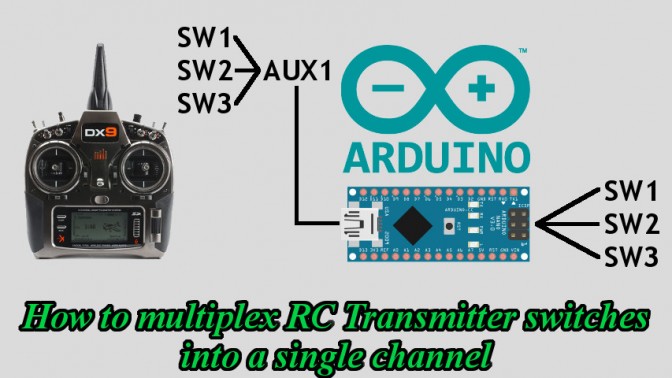
I could have used an 8-channel receiver to solve this but I did not had a free receiver that I could spare. This guide will show you how to multiplex RC transmitter switches (inputs) into a single channel.Use a microcontroller
For this type of project, 7 channels is usually required. The easiest method would have been to replace the receiver but since I like the DIY way, I decided to multiplex two switches into the 6th channel and use a microcontroller to read the signal and demultiplex each switches states.Note: This is only valid if there is a microcontroller connected with the receiver that you can program to demultiplex the signal. Do not expect your proprietary flight controller to be able to understand your signal.
Multiplexing switches (only)
Design
The following section illustrate the design required for multiplexing as much information as possible into a single channel.Create blocks
The generic idea is to divide the whole range of the signal (from -150% to 150%) into blocks or bands. Each block correspond to a unique configuration of all switches. Then you create the required mixes to move/update the signal value to the block corresponding to the switches unique configuration.Minimum number of blocks
The following explain what is the minimum number of blocks that are required for multiplexing a given amount of switches. The number of required blocks for a given number of switches is defined by the all the unique combinations that are possible with the switches. To calculate this, you multiply the number of combinations of each switch by each other. For instance: To multiplex three 2-position switches, 8 blocks are required (2*2*2) which makes 8 unique combinations:| Block Number | Switches | ||
| 2-pos | 2-pos | 2-pos | |
| 0 | 0 | 0 | 0 |
| 1 | 0 | 0 | 1 |
| 2 | 0 | 1 | 0 |
| 3 | 0 | 1 | 1 |
| 4 | 1 | 0 | 0 |
| 5 | 1 | 0 | 1 |
| 6 | 1 | 1 | 0 |
| 7 | 1 | 1 | 1 |
| Block Number | Switches | ||
| 2-pos | 2-pos | 3-pos | |
| 0 | 0 | 0 | 0 |
| 1 | 0 | 0 | 1 |
| 2 | 0 | 0 | 2 |
| 3 | 0 | 1 | 0 |
| 4 | 0 | 1 | 1 |
| 5 | 0 | 1 | 2 |
| 6 | 1 | 0 | 0 |
| 7 | 1 | 0 | 1 |
| 8 | 1 | 0 | 2 |
| 9 | 1 | 1 | 0 |
| 10 | 1 | 1 | 1 |
| 11 | 1 | 1 | 2 |
Note that each switch also requires a mix for working. The amount of switches you can multiplex is then also limited by the amount of mixes you can define in your transmitter.
Supporting 3-position switches
In your design, you will have to decide to support or not 3-position switches. If you do, it will reduce the amount of switches you can multiplex into a single channel since each switches requires 3 blocks instead of 2 blocks. An acceptable compromise is to use this switch as a 2-position switch. Position 1 would then be identical as Position 0 (OFF) and Position 2 would be ON.Dead Zone
Blocks cannot be juxtaposed to each other and dead zones must be inserted between (or within) blocks. This is required since each transmitters and micro-controllers do not offer the same performance and precision. Dead zones are required since a micro-controller might read data from block 5 but the next pulse of the same signal may introduce a 5uS delay, which would correspond to a different block (ie block 6). For instance, if the following blocks are defined:| Block | Min | Max |
| 0 | -150% | -141% |
| 1 | -140% | -131% |
| 2 | -130% | -121% |
| 3 | -120% | -111% |
| Block | Min | Max | Mix Target |
| DEAD | -150% | -148% | |
| 0 | -147% | -143% | -145% |
| DEAD | -142% | -138% | |
| 1 | -137% | -133% | -135% |
| DEAD | -132% | -128% | |
| 2 | -127% | -123% | -125% |
| DEAD | -122% | -113% | |
| 3 | -117% | -113% | -115% |
Block size
Based on my observation, the best values for block size and dead zone size are as follow: A block size of 10 steps is big enough to allow multiplexing a high amount of switches while leaving enough space for a reasonable dead zone between blocks. At the same time, a block size of 10 steps allows the blocks to be rounded easily which makes blocks offsets easy to calculate. The acceptable dead zone size (considering the average precision of most micro-controller and receivers), does not need to be bigger than 2 steps. This configuration leaves two blocks spaced by 4 steps which is enough to prevent issues. The following values are then considered “safe and tested” to get good and stable results:| Block size | : | 10 steps |
| Dead zone | : | 2 steps |
| Effective size | : | 6 steps |
Mixes
The following section defines mix that are required to implement two basic scenarios.Note that you can easily calculate the effect of a given mix by using my RC Transmitter Mix Calculator to identify the minimum, middle and maximum values of a mix.
Four 2-position switches
The following table shows the signal range and the middle of the effective area for each block. It is calculated using a block size of 10 steps and a dead zone of 2 steps which makes the effective block size to 6 steps:| Block Number | Block Offsets | Mix Target | |||||
| Dead | Effective | Dead | |||||
| 0 | -150 | -149 | -148 | -143 | -142 | -141 | -146 |
| 1 | -140 | -139 | -138 | -133 | -132 | -131 | -136 |
| 2 | -130 | -129 | -128 | -123 | -122 | -121 | -126 |
| 3 | -120 | -119 | -118 | -113 | -112 | -111 | -116 |
| 4 | -110 | -109 | -108 | -103 | -102 | -101 | -106 |
| 5 | -100 | -99 | -98 | -93 | -92 | -91 | -96 |
| 6 | -90 | -89 | -88 | -83 | -82 | -81 | -86 |
| 7 | -80 | -79 | -78 | -73 | -72 | -71 | -76 |
| 8 | -70 | -69 | -68 | -63 | -62 | -61 | -66 |
| 9 | -60 | -59 | -58 | -53 | -52 | -51 | -56 |
| 10 | -50 | -49 | -48 | -43 | -42 | -41 | -46 |
| 11 | -40 | -39 | -38 | -33 | -32 | -31 | -36 |
| 12 | -30 | -29 | -28 | -23 | -22 | -21 | -26 |
| 13 | -20 | -19 | -18 | -13 | -12 | -11 | -16 |
| 14 | -10 | -9 | -8 | -3 | -2 | -1 | -6 |
| 15 | 0 | 1 | 2 | 7 | 8 | 9 | 5 |
| Mix info | Mix Output | |||||
| Number | Switch | High | Low | Offset | 0 | 1 |
| 0 | A | -100 | 100 | 0 | -100 | -100 |
| 1 | A | -46 | 36 | 0 | -46 | -36 |
| 2 | B | 0 | -20 | 0 | 0 | 20 |
| 3 | C | 0 | -40 | 0 | 0 | 40 |
| 4 | D | 0 | -80 | 0 | 0 | 80 |
Note that first 2 mix are mapped to switch A. This is required since the minimum value of a High rate mix is -125% which gives a final mix value of -125% at Position 0. The only way to get a lower value (ie -146) would be to offset the mix (by -17) but then the Low rate value would have the same issue.
As you can see, the sum of all combined mixes matches the middle section of each effective block:| Block Number | Switches | Mixes | ||||||||
| D | C | B | A | 0 | 1 | 2 | 3 | 4 | Sum | |
| 0 | 0 | 0 | 0 | 0 | -100 | -46 | 0 | 0 | 0 | -146 |
| 1 | 0 | 0 | 0 | 1 | -100 | -36 | 0 | 0 | 0 | -136 |
| 2 | 0 | 0 | 1 | 0 | -100 | -46 | 20 | 0 | 0 | -126 |
| 3 | 0 | 0 | 1 | 1 | -100 | -36 | 20 | 0 | 0 | -116 |
| 4 | 0 | 1 | 0 | 0 | -100 | -46 | 0 | 40 | 0 | -106 |
| 5 | 0 | 1 | 0 | 1 | -100 | -36 | 0 | 40 | 0 | -96 |
| 6 | 0 | 1 | 1 | 0 | -100 | -46 | 20 | 40 | 0 | -86 |
| 7 | 0 | 1 | 1 | 1 | -100 | -36 | 20 | 40 | 0 | -76 |
| 8 | 1 | 0 | 0 | 0 | -100 | -46 | 0 | 0 | 80 | -66 |
| 9 | 1 | 0 | 0 | 1 | -100 | -36 | 0 | 0 | 80 | -56 |
| 10 | 1 | 0 | 1 | 0 | -100 | -46 | 20 | 0 | 80 | -46 |
| 11 | 1 | 0 | 1 | 1 | -100 | -36 | 20 | 0 | 80 | -36 |
| 12 | 1 | 1 | 0 | 0 | -100 | -46 | 0 | 40 | 80 | -26 |
| 13 | 1 | 1 | 0 | 1 | -100 | -36 | 0 | 40 | 80 | -16 |
| 14 | 1 | 1 | 1 | 0 | -100 | -46 | 20 | 40 | 80 | -6 |
| 15 | 1 | 1 | 1 | 1 | -100 | -36 | 20 | 40 | 80 | 4 |
Three 2-position and one 3-position switches
The following table shows the signal range and the middle of the effective area for each block. It is calculated using a block size of 10 steps and a dead zone of 2 steps which makes the effective block size to 6 steps:| Block Number | Block Offsets | Mix Target | |||||
| Dead | Effective | Dead | |||||
| 0 | -150 | -149 | -148 | -143 | -142 | -141 | -146 |
| 1 | -140 | -139 | -138 | -133 | -132 | -131 | -136 |
| 2 | -130 | -129 | -128 | -123 | -122 | -121 | -126 |
| 3 | -120 | -119 | -118 | -113 | -112 | -111 | -116 |
| 4 | -110 | -109 | -108 | -103 | -102 | -101 | -106 |
| 5 | -100 | -99 | -98 | -93 | -92 | -91 | -96 |
| 6 | -90 | -89 | -88 | -83 | -82 | -81 | -86 |
| 7 | -80 | -79 | -78 | -73 | -72 | -71 | -76 |
| 8 | -70 | -69 | -68 | -63 | -62 | -61 | -66 |
| 9 | -60 | -59 | -58 | -53 | -52 | -51 | -56 |
| 10 | -50 | -49 | -48 | -43 | -42 | -41 | -46 |
| 11 | -40 | -39 | -38 | -33 | -32 | -31 | -36 |
| 12 | -30 | -29 | -28 | -23 | -22 | -21 | -26 |
| 13 | -20 | -19 | -18 | -13 | -12 | -11 | -16 |
| 14 | -10 | -9 | -8 | -3 | -2 | -1 | -6 |
| 15 | 0 | 1 | 2 | 7 | 8 | 9 | 5 |
| 16 | 10 | 11 | 12 | 17 | 18 | 19 | 15 |
| 17 | 20 | 21 | 22 | 27 | 28 | 29 | 25 |
| 18 | 30 | 31 | 32 | 37 | 38 | 39 | 35 |
| 19 | 40 | 41 | 42 | 47 | 48 | 49 | 45 |
| 20 | 50 | 51 | 52 | 57 | 58 | 59 | 55 |
| 21 | 60 | 61 | 62 | 67 | 68 | 69 | 65 |
| 22 | 70 | 71 | 72 | 77 | 78 | 79 | 75 |
| 23 | 80 | 81 | 82 | 87 | 88 | 89 | 85 |
| Mix info | Mix Output | ||||||
| Number | Switch | High | Low | Offset | 0 | 1 | 2 |
| 0 | A | 0 | 68 | 100 | 0 | -68 | -136 |
| 1 | A | -68 | 0 | -100 | -136 | -68 | 0 |
| 2 | A | -10 | -10 | 0 | -10 | 0 | 10 |
| 3 | B | 0 | -30 | 0 | 0 | 30 | |
| 4 | C | 0 | -60 | 0 | 0 | 60 | |
| 5 | D | 0 | -120 | 0 | 0 | 120 | |
Note that first 3 mix are mapped to switch A which is the 3-position switch. The first 2 mix are use to get a constant -136 on all positions. Then the 3rd mix moves the signal value over the first 3 blocks (to the previous, current or next block). As far as I know, there is no way to achieve the same result with only 2 mixes.
As you can see, the sum of all combined mixes matches the middle section of each effective block:| Block Number | Switches | Mixes | |||||||||
| D | C | B | A | 0 | 1 | 2 | 3 | 4 | 5 | Sum | |
| 0 | 0 | 0 | 0 | 0 | 0 | -136 | -10 | 0 | 0 | 0 | -146 |
| 1 | 0 | 0 | 0 | 1 | -68 | -68 | 0 | 0 | 0 | 0 | -136 |
| 2 | 0 | 0 | 0 | 2 | -136 | 0 | 10 | 0 | 0 | 0 | -126 |
| 3 | 0 | 0 | 1 | 0 | 0 | -136 | -10 | 30 | 0 | 0 | -116 |
| 4 | 0 | 0 | 1 | 1 | -68 | -68 | 0 | 30 | 0 | 0 | -106 |
| 5 | 0 | 0 | 1 | 2 | -136 | 0 | 10 | 30 | 0 | 0 | -96 |
| 6 | 0 | 1 | 0 | 0 | 0 | -136 | -10 | 0 | 60 | 0 | -86 |
| 7 | 0 | 1 | 0 | 1 | -68 | -68 | 0 | 0 | 60 | 0 | -76 |
| 8 | 0 | 1 | 0 | 2 | -136 | 0 | 10 | 0 | 60 | 0 | -66 |
| 9 | 0 | 1 | 1 | 0 | 0 | -136 | -10 | 30 | 60 | 0 | -56 |
| 10 | 0 | 1 | 1 | 1 | -68 | -68 | 0 | 30 | 60 | 0 | -46 |
| 11 | 0 | 1 | 1 | 2 | -136 | 0 | 10 | 30 | 60 | 0 | -36 |
| 12 | 1 | 0 | 0 | 0 | 0 | -136 | -10 | 0 | 0 | 120 | -26 |
| 13 | 1 | 0 | 0 | 1 | -68 | -68 | 0 | 0 | 0 | 120 | -16 |
| 14 | 1 | 0 | 0 | 2 | -136 | 0 | 10 | 0 | 0 | 120 | -6 |
| 15 | 1 | 0 | 1 | 0 | 0 | -136 | -10 | 30 | 0 | 120 | 4 |
| 16 | 1 | 0 | 1 | 1 | -68 | -68 | 0 | 30 | 0 | 120 | 14 |
| 17 | 1 | 0 | 1 | 2 | -136 | 0 | 10 | 30 | 0 | 120 | 24 |
| 18 | 1 | 1 | 0 | 0 | 0 | -136 | -10 | 0 | 60 | 120 | 34 |
| 19 | 1 | 1 | 0 | 1 | -68 | -68 | 0 | 0 | 60 | 120 | 44 |
| 20 | 1 | 1 | 0 | 2 | -136 | 0 | 10 | 0 | 60 | 120 | 54 |
| 21 | 1 | 1 | 1 | 0 | 0 | -136 | -10 | 30 | 60 | 120 | 64 |
| 22 | 1 | 1 | 1 | 1 | -68 | -68 | 0 | 30 | 60 | 120 | 74 |
| 23 | 1 | 1 | 1 | 2 | -136 | 0 | 10 | 30 | 60 | 120 | 84 |
Three 3-position switches
The following table shows the signal range and the middle of the effective area for each block. Again, it is calculated using a block size of 10 steps and a dead zone of 2 steps which makes the effective block size to 6 steps:| Block Number | Block Offsets | Mix Target | |||||
| Dead | Effective | Dead | |||||
| 0 | -134 | -133 | -132 | -127 | -126 | -125 | -130 |
| 1 | -124 | -123 | -122 | -117 | -116 | -115 | -120 |
| 2 | -114 | -113 | -112 | -107 | -106 | -105 | -110 |
| 3 | -104 | -103 | -102 | -97 | -96 | -95 | -100 |
| 4 | -94 | -93 | -92 | -87 | -86 | -85 | -90 |
| 5 | -84 | -83 | -82 | -77 | -76 | -75 | -80 |
| 6 | -74 | -73 | -72 | -67 | -66 | -65 | -70 |
| 7 | -64 | -63 | -62 | -57 | -56 | -55 | -60 |
| 8 | -54 | -53 | -52 | -47 | -46 | -45 | -50 |
| 9 | -44 | -43 | -42 | -37 | -36 | -35 | -40 |
| 10 | -34 | -33 | -32 | -27 | -26 | -25 | -30 |
| 11 | -24 | -23 | -22 | -17 | -16 | -15 | -20 |
| 12 | -14 | -13 | -12 | -7 | -6 | -5 | -10 |
| 13 | -4 | -3 | -2 | 3 | 4 | 5 | 1 |
| 14 | 6 | 7 | 8 | 13 | 14 | 15 | 11 |
| 15 | 16 | 17 | 18 | 23 | 24 | 25 | 21 |
| 16 | 26 | 27 | 28 | 33 | 34 | 35 | 31 |
| 17 | 36 | 37 | 38 | 43 | 44 | 45 | 41 |
| 18 | 46 | 47 | 48 | 53 | 54 | 55 | 51 |
| 19 | 56 | 57 | 58 | 63 | 64 | 65 | 61 |
| 20 | 66 | 67 | 68 | 73 | 74 | 75 | 71 |
| 21 | 76 | 77 | 78 | 83 | 84 | 85 | 81 |
| 22 | 86 | 87 | 88 | 93 | 94 | 95 | 91 |
| 23 | 96 | 97 | 98 | 103 | 104 | 105 | 101 |
| 24 | 106 | 107 | 108 | 113 | 114 | 115 | 111 |
| 25 | 116 | 117 | 118 | 123 | 124 | 125 | 121 |
| 26 | 126 | 127 | 128 | 133 | 134 | 135 | 131 |
| Mix info | Mix Output | ||||||
| Number | Switch | High | Low | Offset | 0 | 1 | 2 |
| 0 | A | -10 | -10 | 0 | -10 | 0 | 10 |
| 1 | B | -30 | -30 | 0 | -30 | 0 | 30 |
| 2 | C | -90 | -90 | 0 | -90 | 0 | 90 |
Note that only 3 mix is required for multiplexing three 3-position switches. Mixes are also centered around 0 (instead of starting at -150).
As you can see, the sum of all combined mixes matches the middle section of each effective block:| Block Number | Switches | Mixes | |||||
| C | B | A | 0 | 1 | 2 | Sum | |
| 0 | 0 | 0 | 0 | -10 | -30 | -90 | -130 |
| 1 | 0 | 0 | 1 | 0 | -30 | -90 | -120 |
| 2 | 0 | 0 | 2 | 10 | -30 | -90 | -110 |
| 3 | 0 | 1 | 0 | -10 | 0 | -90 | -100 |
| 4 | 0 | 1 | 1 | 0 | 0 | -90 | -90 |
| 5 | 0 | 1 | 2 | 10 | 0 | -90 | -80 |
| 6 | 0 | 2 | 0 | -10 | 30 | -90 | -70 |
| 7 | 0 | 2 | 1 | 0 | 30 | -90 | -60 |
| 8 | 0 | 2 | 2 | 10 | 30 | -90 | -50 |
| 9 | 1 | 0 | 0 | -10 | -30 | 0 | -40 |
| 10 | 1 | 0 | 1 | 0 | -30 | 0 | -30 |
| 11 | 1 | 0 | 2 | 10 | -30 | 0 | -20 |
| 12 | 1 | 1 | 0 | -10 | 0 | 0 | -10 |
| 13 | 1 | 1 | 1 | 0 | 0 | 0 | 0 |
| 14 | 1 | 1 | 2 | 10 | 0 | 0 | 10 |
| 15 | 1 | 2 | 0 | -10 | 30 | 0 | 20 |
| 16 | 1 | 2 | 1 | 0 | 30 | 0 | 30 |
| 17 | 1 | 2 | 2 | 10 | 30 | 0 | 40 |
| 18 | 2 | 0 | 0 | -10 | -30 | 90 | 50 |
| 19 | 2 | 0 | 1 | 0 | -30 | 90 | 60 |
| 20 | 2 | 0 | 2 | 10 | -30 | 90 | 70 |
| 21 | 2 | 1 | 0 | -10 | 0 | 90 | 80 |
| 22 | 2 | 1 | 1 | 0 | 0 | 90 | 90 |
| 23 | 2 | 1 | 2 | 10 | 0 | 90 | 100 |
| 24 | 2 | 2 | 0 | -10 | 30 | 90 | 110 |
| 25 | 2 | 2 | 1 | 0 | 30 | 90 | 120 |
| 26 | 2 | 2 | 2 | 10 | 30 | 90 | 130 |
Decoding
Decoding the switches configuration is relatively easy: First identify the block number matching the signal’s value using a sequence of “if” statements. Then, update switches state based on the currently selected block. Refer to tables above for offsets & switches states for each selected block.Note that if you get a signal value that is within the dead zone, it probably means that you have an issue with your transmitter mixes. Verify your mixes and try again.
Since reading switches states does not imply any analog value, you do not really care if the signal value is within the effective area (or not) so clamping is not necessary beside detecting instability issue in the signal. However, in the low probability that you get a signal within a dead zone, then the first dead zone should be considered as if you read the first value of the effective area and the last dead zone as the last value of the effective area.Required Libraries
PinChangeInt This library allows the arduino to attach interrupts on multiple pins. eRCaGuy_Timer2_Counter (optional) This library configures the arduino’s timer2 to 0.5µs precision. It is used for a micros() function replacement and allows times calculations that are far more precise (8 times!) than the default’s 4µs resolution.Code sample
The following arduino code (*.ino) can be used to demultiplex the three scenarios above:|
1 2 3 4 5 6 7 8 9 10 11 12 13 14 15 16 17 18 19 20 21 22 23 24 25 26 27 28 29 30 31 32 33 34 35 36 37 38 39 40 41 42 43 44 45 46 47 48 49 50 51 52 53 54 55 56 57 58 59 60 61 62 63 64 65 66 67 68 69 70 71 72 73 74 75 76 77 78 79 80 81 82 83 84 85 86 87 88 89 90 91 92 93 94 95 96 97 98 99 100 101 102 103 104 105 106 107 108 109 110 111 112 113 114 115 116 117 118 119 120 121 122 123 124 125 126 127 128 129 130 131 132 133 134 135 136 137 138 139 140 141 142 143 144 145 146 147 148 149 150 151 152 153 154 155 156 157 158 159 160 161 162 163 164 165 166 167 168 169 170 171 172 173 174 175 176 177 178 179 180 181 182 183 184 185 186 187 188 189 190 191 192 193 194 195 196 197 198 199 200 201 202 203 204 205 206 207 208 209 210 211 212 213 214 215 216 217 218 |
//Using RcReceiverSignal v1.1.203 //required to read the receiver's value //available at http://www.end2endzone.com/rcreceiversignal-an-arduino-library-for-retreiving-the-rc-transmitter-value-from-an-rc-receiver-pulse/ #include <RcReceiverSignal.h> //Using PinChangeInt version 2402 //RcReceiverSignal library has a dependency to PinChangeInt library. //available at http://code.google.com/p/arduino-pinchangeint/ #include <PinChangeInt.h> //Using eRCaGuy_Timer2_Counter version 20140709 (last updated 9 July 2014) //Required to have a micros() replacement function which has a //1us resolution instead of 4usec. //For more information on this library, see the following: // http://electricrcaircraftguy.com/2014/02/Timer2Counter-more-precise-Arduino-micros-function.html // http://www.instructables.com/id/How-to-get-an-Arduino-micros-function-with-05us-pr/ #include <eRCaGuy_Timer2_Counter.h> //project's constants #define RECEIVER_AUX1_IN_PIN 2 // we could choose any pin //project's switches #define ENABLE_SERIAL_OUTPUT //***************************************************************************** // TODO: UNCOMMENT ONE OF THE FOLLOWING: //****************************************************************************/ //#define _4X2POS //#define _3X2POS1X3POS //#define _3X3POS DECLARE_RECEIVER_SIGNAL(receiver_aux1_handler); inline short clamp(const short & iMin, const short & iValue, const short & iMax) { if (iValue < iMin) return iMin; if (iValue > iMax) return iMax; return iValue; } void demultiplex4x2Pos(const short & iSignal, bool & oSwitchA, bool & oSwitchB, bool & oSwitchC, bool & oSwitchD) { #define setSwitches(d,c,b,a) oSwitchA=(a==1); oSwitchB=(b==1); oSwitchC=(c==1); oSwitchD=(d==1); if ( -150 <= iSignal && iSignal <= -141 ) { setSwitches( 0 , 0 , 0 , 0 ) } else if ( -140 <= iSignal && iSignal <= -131 ) { setSwitches( 0 , 0 , 0 , 1 ) } else if ( -130 <= iSignal && iSignal <= -121 ) { setSwitches( 0 , 0 , 1 , 0 ) } else if ( -120 <= iSignal && iSignal <= -111 ) { setSwitches( 0 , 0 , 1 , 1 ) } else if ( -110 <= iSignal && iSignal <= -101 ) { setSwitches( 0 , 1 , 0 , 0 ) } else if ( -100 <= iSignal && iSignal <= -91 ) { setSwitches( 0 , 1 , 0 , 1 ) } else if ( -90 <= iSignal && iSignal <= -81 ) { setSwitches( 0 , 1 , 1 , 0 ) } else if ( -80 <= iSignal && iSignal <= -71 ) { setSwitches( 0 , 1 , 1 , 1 ) } else if ( -70 <= iSignal && iSignal <= -61 ) { setSwitches( 1 , 0 , 0 , 0 ) } else if ( -60 <= iSignal && iSignal <= -51 ) { setSwitches( 1 , 0 , 0 , 1 ) } else if ( -50 <= iSignal && iSignal <= -41 ) { setSwitches( 1 , 0 , 1 , 0 ) } else if ( -40 <= iSignal && iSignal <= -31 ) { setSwitches( 1 , 0 , 1 , 1 ) } else if ( -30 <= iSignal && iSignal <= -21 ) { setSwitches( 1 , 1 , 0 , 0 ) } else if ( -20 <= iSignal && iSignal <= -11 ) { setSwitches( 1 , 1 , 0 , 1 ) } else if ( -10 <= iSignal && iSignal <= -1 ) { setSwitches( 1 , 1 , 1 , 0 ) } else if ( 0 <= iSignal && iSignal <= 9 ) { setSwitches( 1 , 1 , 1 , 1 ) } else { setSwitches(0,0,0,0); } #undef setSwitches } void demultiplex3x2Pos1x3Pos(const short & iSignal, unsigned char & oSwitchA, bool & oSwitchB, bool & oSwitchC, bool & oSwitchD) { #define setSwitches(d,c,b,a) oSwitchA=a; oSwitchB=(b==1); oSwitchC=(c==1); oSwitchD=(d==1); if ( -150 <= iSignal && iSignal <= -141 ) { setSwitches( 0 , 0 , 0 , 0 ) } else if ( -140 <= iSignal && iSignal <= -131 ) { setSwitches( 0 , 0 , 0 , 1 ) } else if ( -130 <= iSignal && iSignal <= -121 ) { setSwitches( 0 , 0 , 0 , 2 ) } else if ( -120 <= iSignal && iSignal <= -111 ) { setSwitches( 0 , 0 , 1 , 0 ) } else if ( -110 <= iSignal && iSignal <= -101 ) { setSwitches( 0 , 0 , 1 , 1 ) } else if ( -100 <= iSignal && iSignal <= -91 ) { setSwitches( 0 , 0 , 1 , 2 ) } else if ( -90 <= iSignal && iSignal <= -81 ) { setSwitches( 0 , 1 , 0 , 0 ) } else if ( -80 <= iSignal && iSignal <= -71 ) { setSwitches( 0 , 1 , 0 , 1 ) } else if ( -70 <= iSignal && iSignal <= -61 ) { setSwitches( 0 , 1 , 0 , 2 ) } else if ( -60 <= iSignal && iSignal <= -51 ) { setSwitches( 0 , 1 , 1 , 0 ) } else if ( -50 <= iSignal && iSignal <= -41 ) { setSwitches( 0 , 1 , 1 , 1 ) } else if ( -40 <= iSignal && iSignal <= -31 ) { setSwitches( 0 , 1 , 1 , 2 ) } else if ( -30 <= iSignal && iSignal <= -21 ) { setSwitches( 1 , 0 , 0 , 0 ) } else if ( -20 <= iSignal && iSignal <= -11 ) { setSwitches( 1 , 0 , 0 , 1 ) } else if ( -10 <= iSignal && iSignal <= -1 ) { setSwitches( 1 , 0 , 0 , 2 ) } else if ( 0 <= iSignal && iSignal <= 9 ) { setSwitches( 1 , 0 , 1 , 0 ) } else if ( 10 <= iSignal && iSignal <= 19 ) { setSwitches( 1 , 0 , 1 , 1 ) } else if ( 20 <= iSignal && iSignal <= 29 ) { setSwitches( 1 , 0 , 1 , 2 ) } else if ( 30 <= iSignal && iSignal <= 39 ) { setSwitches( 1 , 1 , 0 , 0 ) } else if ( 40 <= iSignal && iSignal <= 49 ) { setSwitches( 1 , 1 , 0 , 1 ) } else if ( 50 <= iSignal && iSignal <= 59 ) { setSwitches( 1 , 1 , 0 , 2 ) } else if ( 60 <= iSignal && iSignal <= 69 ) { setSwitches( 1 , 1 , 1 , 0 ) } else if ( 70 <= iSignal && iSignal <= 79 ) { setSwitches( 1 , 1 , 1 , 1 ) } else if ( 80 <= iSignal && iSignal <= 89 ) { setSwitches( 1 , 1 , 1 , 2 ) } else { setSwitches(0,0,0,0); } #undef setSwitches } void demultiplex3x3Pos(const short & iSignal, unsigned char & oSwitchA, unsigned char & oSwitchB, unsigned char & oSwitchC) { #define setSwitches(c,b,a) oSwitchA=a; oSwitchB=b; oSwitchC=c; if ( -134 <= iSignal && iSignal <= -125 ) { setSwitches( 0 , 0 , 0 ) } else if ( -124 <= iSignal && iSignal <= -115 ) { setSwitches( 0 , 0 , 1 ) } else if ( -114 <= iSignal && iSignal <= -105 ) { setSwitches( 0 , 0 , 2 ) } else if ( -104 <= iSignal && iSignal <= -95 ) { setSwitches( 0 , 1 , 0 ) } else if ( -94 <= iSignal && iSignal <= -85 ) { setSwitches( 0 , 1 , 1 ) } else if ( -84 <= iSignal && iSignal <= -75 ) { setSwitches( 0 , 1 , 2 ) } else if ( -74 <= iSignal && iSignal <= -65 ) { setSwitches( 0 , 2 , 0 ) } else if ( -64 <= iSignal && iSignal <= -55 ) { setSwitches( 0 , 2 , 1 ) } else if ( -54 <= iSignal && iSignal <= -45 ) { setSwitches( 0 , 2 , 2 ) } else if ( -44 <= iSignal && iSignal <= -35 ) { setSwitches( 1 , 0 , 0 ) } else if ( -34 <= iSignal && iSignal <= -25 ) { setSwitches( 1 , 0 , 1 ) } else if ( -24 <= iSignal && iSignal <= -15 ) { setSwitches( 1 , 0 , 2 ) } else if ( -14 <= iSignal && iSignal <= -5 ) { setSwitches( 1 , 1 , 0 ) } else if ( -4 <= iSignal && iSignal <= 5 ) { setSwitches( 1 , 1 , 1 ) } else if ( 6 <= iSignal && iSignal <= 15 ) { setSwitches( 1 , 1 , 2 ) } else if ( 16 <= iSignal && iSignal <= 25 ) { setSwitches( 1 , 2 , 0 ) } else if ( 26 <= iSignal && iSignal <= 35 ) { setSwitches( 1 , 2 , 1 ) } else if ( 36 <= iSignal && iSignal <= 45 ) { setSwitches( 1 , 2 , 2 ) } else if ( 46 <= iSignal && iSignal <= 55 ) { setSwitches( 2 , 0 , 0 ) } else if ( 56 <= iSignal && iSignal <= 65 ) { setSwitches( 2 , 0 , 1 ) } else if ( 66 <= iSignal && iSignal <= 75 ) { setSwitches( 2 , 0 , 2 ) } else if ( 76 <= iSignal && iSignal <= 85 ) { setSwitches( 2 , 1 , 0 ) } else if ( 86 <= iSignal && iSignal <= 95 ) { setSwitches( 2 , 1 , 1 ) } else if ( 96 <= iSignal && iSignal <= 105 ) { setSwitches( 2 , 1 , 2 ) } else if ( 106 <= iSignal && iSignal <= 115 ) { setSwitches( 2 , 2 , 0 ) } else if ( 116 <= iSignal && iSignal <= 125 ) { setSwitches( 2 , 2 , 1 ) } else if ( 126 <= iSignal && iSignal <= 135 ) { setSwitches( 2 , 2 , 2 ) } else { setSwitches(0,0,0); } #undef setSwitches } uint32_t timer2GetCountWrapperFunction() { return timer2.get_count(); } void setup() { //configure Timer2 timer2.setup(); //this MUST be done before the other Timer2_Counter functions work; Note: since this messes up PWM outputs on pins 3 & 11, as well as //interferes with the tone() library (http://arduino.cc/en/reference/tone), you can always revert Timer2 back to normal by calling //timer2.unsetup() //configure RcReceiverSignal with an external time counter //eRCaGuy_Timer2_Counter lirary has 0.5us resolution. //The counter value must be divided by 2 to convert from 0.5us steps to 1us steps //which results in microseconds resolution. RcReceiverSignal::setExternalTimeCounter(&timer2GetCountWrapperFunction, 1, 2); //link RcReceiverSignal to use PinChangeInt library RcReceiverSignal::setAttachInterruptFunction(&PCintPort::attachInterrupt); RcReceiverSignal::setPinStatePointer(&PCintPort::pinState); #ifdef ENABLE_SERIAL_OUTPUT Serial.begin(115200); Serial.println("ready"); #endif receiver_aux1_handler_setup(RECEIVER_AUX1_IN_PIN); } void loop() { //detect when the receiver AUX1 value has changed if (receiver_aux1_handler.hasChanged()) { unsigned long pwmValue = receiver_aux1_handler.getPwmValue(); RcReceiverSignal::VALUE signal = receiver_aux1_handler.getSignalValue(pwmValue); char buffer[100]; #ifdef _4X2POS bool switchA = false; bool switchB = false; bool switchC = false; bool switchD = false; demultiplex4x2Pos(signal, switchA, switchB, switchC, switchD); //print switches state sprintf(buffer, "PWM=%04d s=%04d A=%d B=%d C=%d D=%d", (int)pwmValue, (int)signal, switchA, switchB, switchC, switchD); #endif #ifdef _3X2POS1X3POS unsigned char switchA = 0; bool switchB = false; bool switchC = false; bool switchD = false; demultiplex3x2Pos1x3Pos(signal, switchA, switchB, switchC, switchD); //print switches state sprintf(buffer, "PWM=%04d s=%04d A=%d B=%d C=%d D=%d", (int)pwmValue, (int)signal, switchA, switchB, switchC, switchD); #endif #ifdef _3X3POS unsigned char switchA = 0; unsigned char switchB = 0; unsigned char switchC = 0; demultiplex3x3Pos(signal, switchA, switchB, switchC); //print switches state sprintf(buffer, "PWM=%04d s=%04d A=%d B=%d C=%d", (int)pwmValue, (int)signal, switchA, switchB, switchC); #endif Serial.println(buffer); } } |
Sample data
-
 559x527
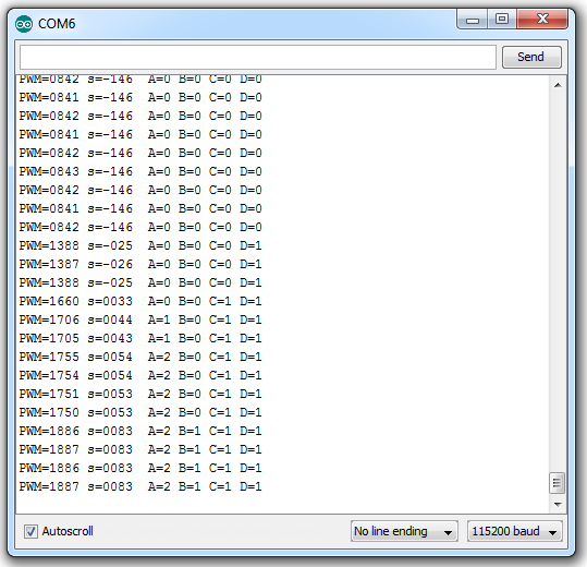
- Demultiplexing four 2-position switches : Sample data

-
 539x520
- Demultiplexing a 3-Position and three 2-Position switches : Sample data
Demultiplexing a 3-Position and three 2-Position switches : Sample data
-
 533x514
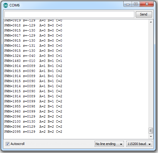
- Demultiplexing three 3-Position switches : Sample data
Demultiplexing three 3-Position switches : Sample data
Multiplexing an analog input and switches
Design
Including an analog value (usually a rotating knob) into the multiplexed signal is also possible. However, only a single analog value can be multiplexed.Please note that including an analog value reduces the number of switches that can be multiplexed into the signal.
Define resolution
Defining the resolution of the analog value means that you must choose the granularity of the value. By default the analog value has at least 200 different values and ranges from -100% to +100%. Since you also want to multiplex switches into the same signal, the resolution must be reduced from 200 different values to a lot less. To support a desired resolution, multiple blocks will need to be sacrificed. I do recommend a resolution of 40 steps (with values from 0 to 39) which is a nice resolution to allow enough details and can also be subdivided into other zones.What’s different
The design for including an analog value is different than having only switches.Block size
Block size must be increased to allow the desired resolution. The higher the resolution, the less switches you can multiplex. The block size must be big enough to fit both dead zones and the desired resolution.Dead zone
A dead zone of 3 steps is also suggested. For instance, to support a resolution of 40 different steps, the block size must be of 46 steps (3+40+3=46). The following table shows the signal range and the middle of the effective area for each block. It is calculated using a block size of 46 steps and a dead zone of 3 steps which makes the effective block size to 40 steps:| Block Number | Block Offsets | |||||
| Dead | Effective | Dead | ||||
| 0 | -150 | -148 | -147 | -108 | -107 | -105 |
| 1 | -104 | -102 | -101 | -62 | -61 | -59 |
| 2 | -58 | -56 | -55 | -16 | -15 | -13 |
| 3 | -12 | -10 | -9 | 30 | 31 | 33 |
| 4 | 34 | 36 | 37 | 76 | 77 | 79 |
| 5 | 80 | 82 | 83 | 122 | 123 | 125 |
- 2-position switch + 3-position switch
- Two 2-position switches
Mixes
When multiplexing an analog value, mixes do not have to target the middle of the block’s effective zone (as with switches) since the signal’s value can move within the whole effective area of the block. Assuming the first configuration (2-pos + 3-pos), the following mixes must be created to multiplex all switches unique configurations:| Mix info | Mix Output | ||||||
| Number | Switch | High | Low | Offset | 0 | 1 | 2 |
| 0 | RKnob | -74 | 0 | -99 | -147 | -73 | 0 |
| 1 | RKnob | 0 | 54 | 100 | 0 | -54 | -108 |
| 2 | A | 0 | -69 | 100 | 0 | 138 | |
| 3 | B | 0 | -46 | 100 | 0 | 46 | 92 |
Note that first 2 mix are mapped to the right knob to reach the effective range of the first block (-147% to -108%). Switch B is a 3-position switch and offsets the analog range between block 0 to 2. Then the 3rd mix, assigned to Switch A (2-position), offsets the 3 effective block of switch B to block 0-2 or 3-5.
As you can see, the sum of all combined mixes matches the middle section of each effective block:| Block Number | Switches | Mixes | ||||||
| A | B | RKnob | 0 | 1 | 2 | 3 | Sum | |
| 0 | 0 | 0 | 0 | -147 | 0 | 0 | 0 | -147 |
| 0 | 0 | 0 | 40 | 0 | -108 | 0 | 0 | -108 |
| 1 | 0 | 1 | 0 | -147 | 0 | 0 | 46 | -101 |
| 1 | 0 | 1 | 40 | 0 | -108 | 0 | 46 | -62 |
| 2 | 0 | 2 | 0 | -147 | 0 | 0 | 92 | -55 |
| 2 | 0 | 2 | 40 | 0 | -108 | 0 | 92 | -16 |
| 3 | 1 | 0 | 0 | -147 | 0 | 138 | 0 | -9 |
| 3 | 1 | 0 | 40 | 0 | -108 | 138 | 0 | 30 |
| 4 | 1 | 1 | 0 | -147 | 0 | 138 | 46 | 37 |
| 4 | 1 | 1 | 40 | 0 | -108 | 138 | 46 | 76 |
| 5 | 1 | 2 | 0 | -147 | 0 | 138 | 92 | 83 |
| 5 | 1 | 2 | 40 | 0 | -108 | 138 | 92 | 122 |
Decoding
Decoding an analog value with switches configuration is different: First identify the block number matching the signal’s value using a sequence of “if” statements. Then clamp the value within the effective block area. This is required since the signal can get close to a dead zone (or even reach a dead zone!). To get the actual analog value, you must also offset the block’s effective range to get a constant 0-39 range. Finally, update switches state based on the currently selected block. Refer to tables above for offsets & switches states for each selected block.Note that reading a value (with the micro-controller) that is outside the analog effective area should be considered the same as reading an analog value of 0 or 39 depending on the closest dead zone.
Code sample
The following arduino code (*.ino) can be used to demultiplex the scenario above:|
1 2 3 4 5 6 7 8 9 10 11 12 13 14 15 16 17 18 19 20 21 22 23 24 25 26 27 28 29 30 31 32 33 34 35 36 37 38 39 40 41 42 43 44 45 46 47 48 49 50 51 52 53 54 55 56 57 58 59 60 61 62 63 64 65 66 67 68 69 70 71 72 73 74 75 76 77 78 79 80 81 82 83 84 85 86 87 88 89 90 91 92 93 94 95 96 97 98 99 100 101 |
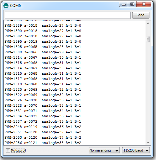
//Using RcReceiverSignal v1.1.203 //required to read the receiver's value //available at http://www.end2endzone.com/rcreceiversignal-an-arduino-library-for-retreiving-the-rc-transmitter-value-from-an-rc-receiver-pulse/ #include <RcReceiverSignal.h> //Using PinChangeInt version 2402 //RcReceiverSignal library has a dependency to PinChangeInt library. //available at http://code.google.com/p/arduino-pinchangeint/ #include <PinChangeInt.h> //Using eRCaGuy_Timer2_Counter version 20140709 (last updated 9 July 2014) //Required to have a micros() replacement function which has a //1us resolution instead of 4usec. //For more information on this library, see the following: // http://electricrcaircraftguy.com/2014/02/Timer2Counter-more-precise-Arduino-micros-function.html // http://www.instructables.com/id/How-to-get-an-Arduino-micros-function-with-05us-pr/ #include <eRCaGuy_Timer2_Counter.h> //project's constants #define RECEIVER_AUX1_IN_PIN 2 // we could choose any pin //project's switches #define ENABLE_SERIAL_OUTPUT DECLARE_RECEIVER_SIGNAL(receiver_aux1_handler); inline short clamp(const short & iMin, const short & iValue, const short & iMax) { if (iValue < iMin) return iMin; if (iValue > iMax) return iMax; return iValue; } void demultiplexAnalog40_1x2Pos1x3Pos(const short & iSignal, unsigned char & oAnalogA, bool & oSwitch2, unsigned char & oSwitch3) { #define setSwitches(effectiveMin,signal,effectiveMax,a,b) oAnalogA=clamp(effectiveMin,signal,effectiveMax) - (effectiveMin); oSwitch2=a; oSwitch3=b; if ( -150 <= iSignal && iSignal <= -105 ) { setSwitches( -147 ,iSignal, -108, 0, 0 ) } else if ( -104 <= iSignal && iSignal <= -59 ) { setSwitches( -101 ,iSignal, -62, 0, 1 ) } else if ( -58 <= iSignal && iSignal <= -13 ) { setSwitches( -55 ,iSignal, -16, 0, 2 ) } else if ( -12 <= iSignal && iSignal <= 33 ) { setSwitches( -9 ,iSignal, 30, 1, 0 ) } else if ( 34 <= iSignal && iSignal <= 79 ) { setSwitches( 37 ,iSignal, 76, 1, 1 ) } else if ( 80 <= iSignal && iSignal <= 125 ) { setSwitches( 83 ,iSignal, 122, 1, 2 ) } else { setSwitches( 0,0,0,0,0 ); } #undef setSwitches } uint32_t timer2GetCountWrapperFunction() { return timer2.get_count(); } void setup() { //configure Timer2 timer2.setup(); //this MUST be done before the other Timer2_Counter functions work; Note: since this messes up PWM outputs on pins 3 & 11, as well as //interferes with the tone() library (http://arduino.cc/en/reference/tone), you can always revert Timer2 back to normal by calling //timer2.unsetup() //configure RcReceiverSignal with an external time counter //eRCaGuy_Timer2_Counter lirary has 0.5us resolution. //The counter value must be divided by 2 to convert from 0.5us steps to 1us steps //which results in microseconds resolution. RcReceiverSignal::setExternalTimeCounter(&timer2GetCountWrapperFunction, 1, 2); //link RcReceiverSignal to use PinChangeInt library RcReceiverSignal::setAttachInterruptFunction(&PCintPort::attachInterrupt); RcReceiverSignal::setPinStatePointer(&PCintPort::pinState); #ifdef ENABLE_SERIAL_OUTPUT Serial.begin(115200); Serial.println("ready"); #endif receiver_aux1_handler_setup(RECEIVER_AUX1_IN_PIN); } void loop() { //detect when the receiver AUX1 value has changed if (receiver_aux1_handler.hasChanged()) { unsigned long pwmValue = receiver_aux1_handler.getPwmValue(); RcReceiverSignal::VALUE signal = receiver_aux1_handler.getSignalValue(pwmValue); char buffer[100]; unsigned char analogA = 0; bool switch2 = 0; unsigned char switch3 = 0; demultiplexAnalog40_1x2Pos1x3Pos(signal, analogA, switch2, switch3); //print switches state sprintf(buffer, "PWM=%04d s=%04d analogA=%2d A=%d B=%d", (int)pwmValue, (int)signal, analogA, switch2, switch3); Serial.println(buffer); } } |
Sample data
-
 498x510
- Demultiplexing an analog knob with a 2-Position and a 3-Position switch : Sample data
Demultiplexing an analog knob with a 2-Position and a 3-Position switch : Sample data