Introduction
I have been working on multiple projects since I bought my camera. Most of them are related to super telephoto shots, macrophotography. Other requires a very long exposures or even a bulb exposure modes.
For all these kind of photography, camera shake is your greatest enemy. You really need to reduce the shaking to a minimum. The first element I bought to reduce camera shake was a tripod but that wasn’t enough. When pressing the shutter button, a light shake was induced by my fingers and that would sometime ruin the image.
For solving this issue, most camera allows the user to set a delay for taking a picture. That is perfect alternative for situation where the scene you are photographing does not change a lot or is predictable like macrophotography or long exposures scenarios. However, it is not suitable for wild life super telephoto shots or when you need the bulb mode since you have to hold and release the shutter for the whole exposure.
Canon sells a Remote Switch RS-60E3 which acts exactly like your shutter button, enabling halfway or complete pressing for adjusting auto-focus or activating the shutter to capture an image. It sells for 34$ (at the time of this writing) but it is only 2-ft long.
Since the Canon version is not exactly what I needed, I though why not create one instead of buying it. In this article, I will show you how I built a DIY version of Canon’s remote shutter release cable for my Canon DSLR camera.
On most Canon cameras, you can make a DIY remote trigger version by connecting a simple 2.5mm stereo plug into your camera and shorting the longest pin with one of the shortest pin.
Making one of these is a simple task. I decided to use the DIY way because I get the opportunity to build the device with more flexibility than the original with a longer cable. At the same time, it is much more satisfying since the build cost will be smaller than buying the real device which is normally the opposite.
Project data
Equipment
The material for this project is as follows:
- 2 momentary switches.
- At least 5 ft of 3-wire cable.
- A small project box
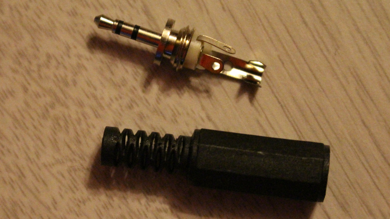
- A 2.5 mm male stereo audio plug
Switches
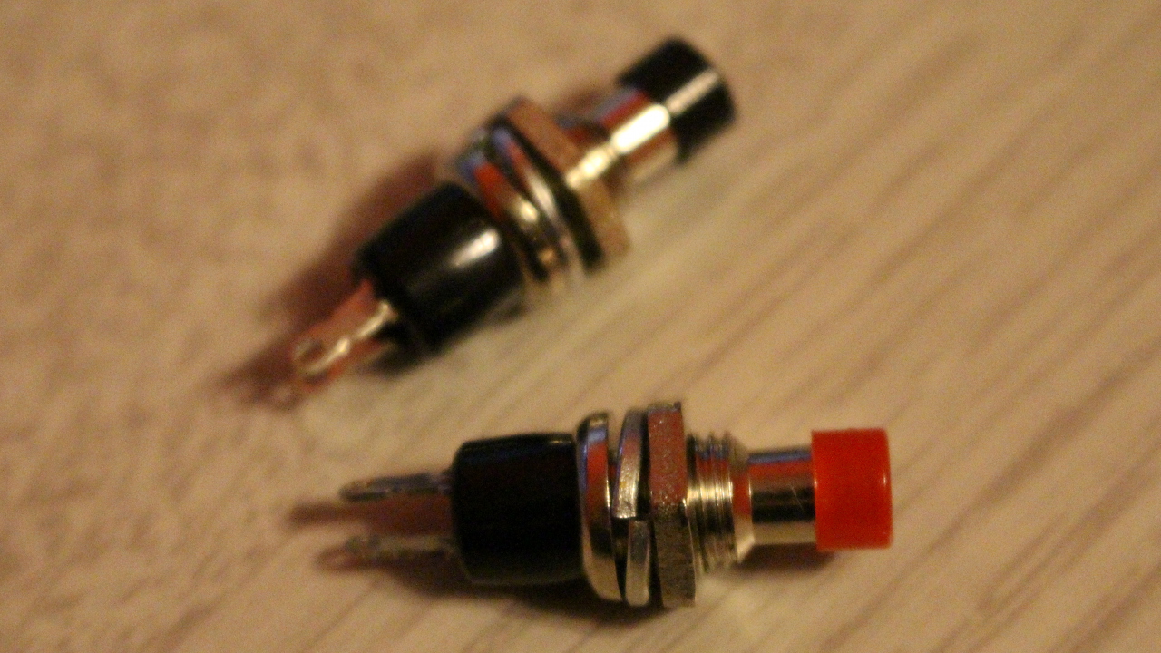
Black and red momentary switches
Switches can be any type you want as long as its a momentary switch (normally opened, push to close). I do recommend to have different colors for assigning auto-focus and shutter buttons to a wire color. I used these switches from eBay. They are cheap and are ready for mounting to a hard surface.
Cable
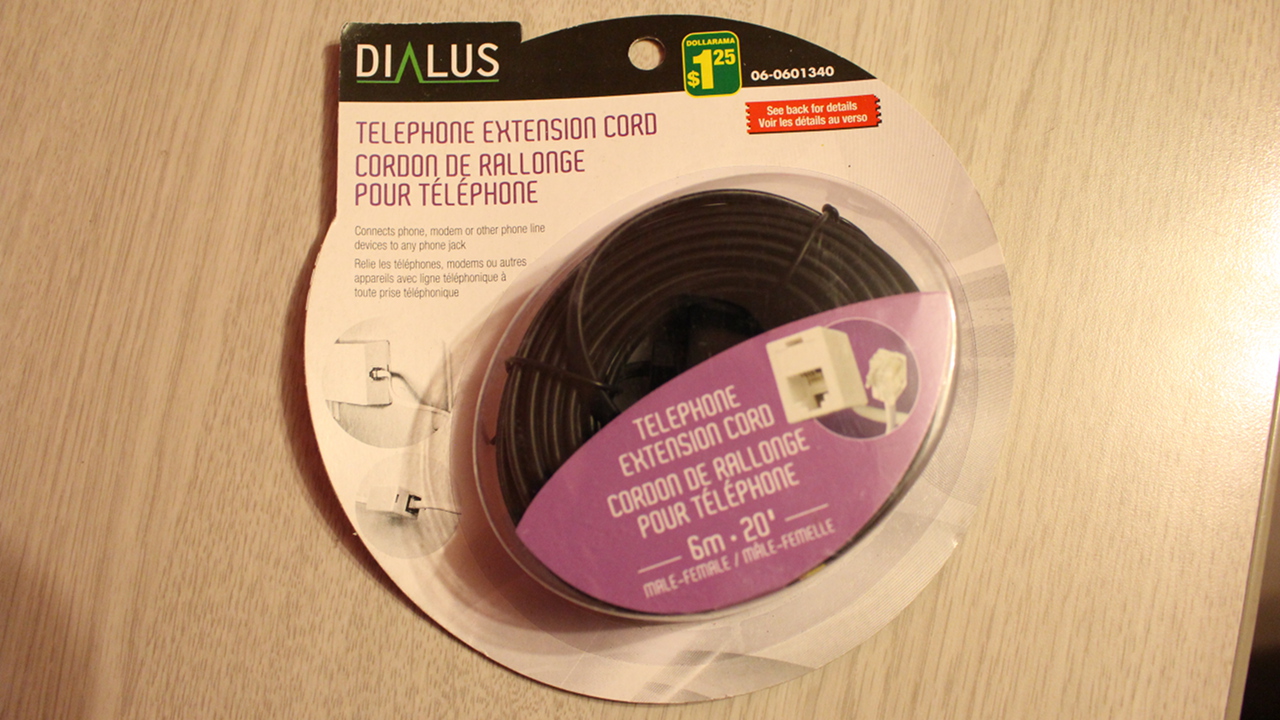
20 feet telephone extension cord
You can use any type of cable as long as it have at least 3 colored wires. you basically have to extend the connections of the 2.5 mm plug. I decided to go with a 20 feet phone cable because it is cheap and easily available. Make sure the cable is not too rough and can bent without too much force because you do not want to move your camera while you are pulling or raising your trigger.
Project box
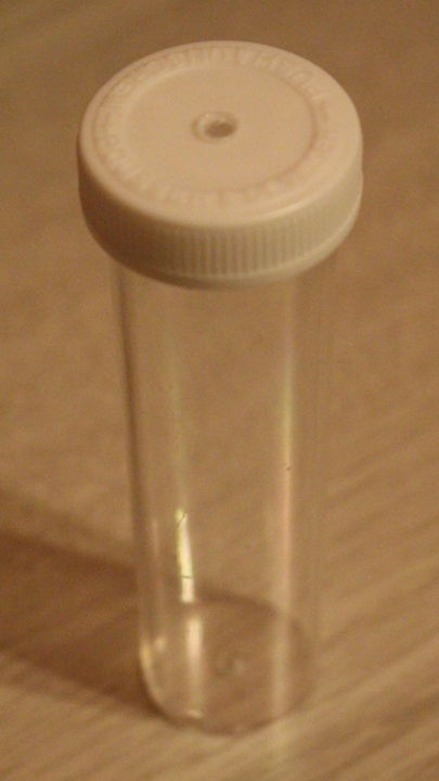
Crazy glue box
The project box is used for the switches. It can be anything as long as you can drill holes big enough for mounting the switches on. It also has to be small enough to be held in one hand. I decided to use a super glue container which is the perfect size for fitting in my hands.
Other material

Total cost of the project
This project is really cheap and can be completed with less than 10$.
Here is the detailed price of each items:
- 4.00$ – Switches
- 1.25$ – Cable
- 1.00$ – Project box
- 2.00$ – Audio plug
Total cost: $8.25
* The cost of usual items such as screws and glue is not included in the cost of the project.
Preparation time
The whole project can be completed in 3 hours.
The preparation time is simple. It requires you to evaluate the feasibility of the project by testing the functionality of the remote trigger on your camera. You want to know the behavior of your camera before beginning everything else!
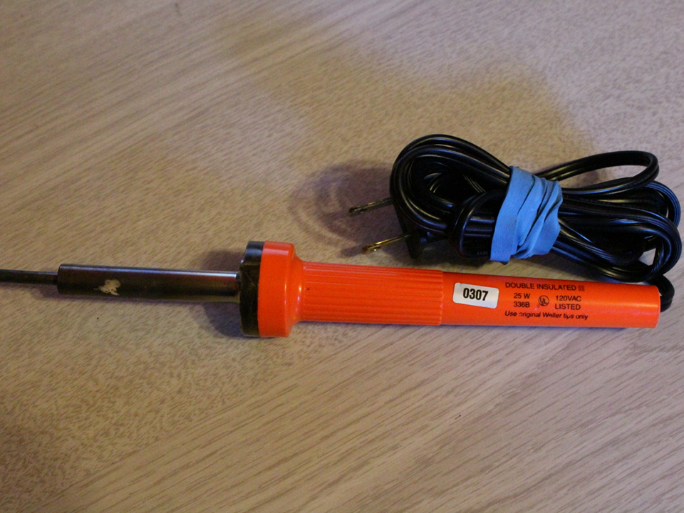
This project also requires you to have soldering skills so your mileage may vary. The duration of this project may change depending on how much you are comfortable with a soldering iron.
Building steps
Construction steps are very simple. Screw, wire everything up, solder and enjoy.
Testing the remote trigger on your camera
This is the first step and allows you to verify if your camera will properly react to the auto-focus and shutter commands.
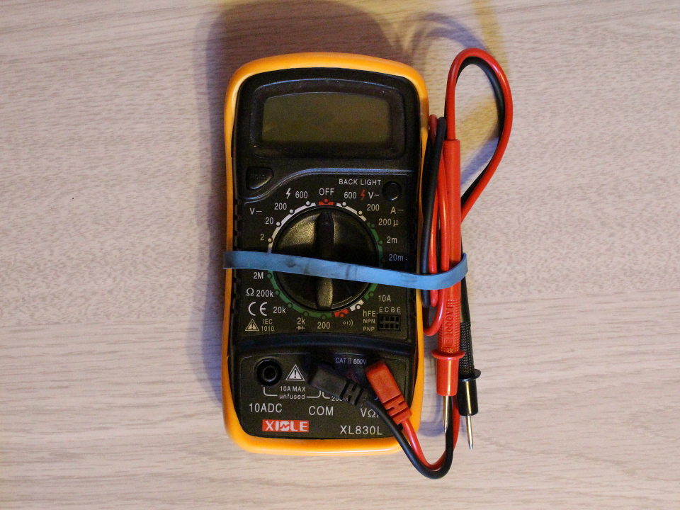
Use the audio plug and take off the protective cover of the 2.5 mm stereo plug leaving the connectors naked and connect it into your camera. Use a small wire or a metal object and short-circuit (connect) the longest pin with one of the shortest pin for half a second. If you are afraid of breaking something, you can use the multimeter set to “Continuity” and connect the probes to each pins. One pin should activate the auto-focus feature and let you ear the easily recognizable beeping sound. The other should activate the shutter and trigger the camera to take a photo.
Soldering the audio plug
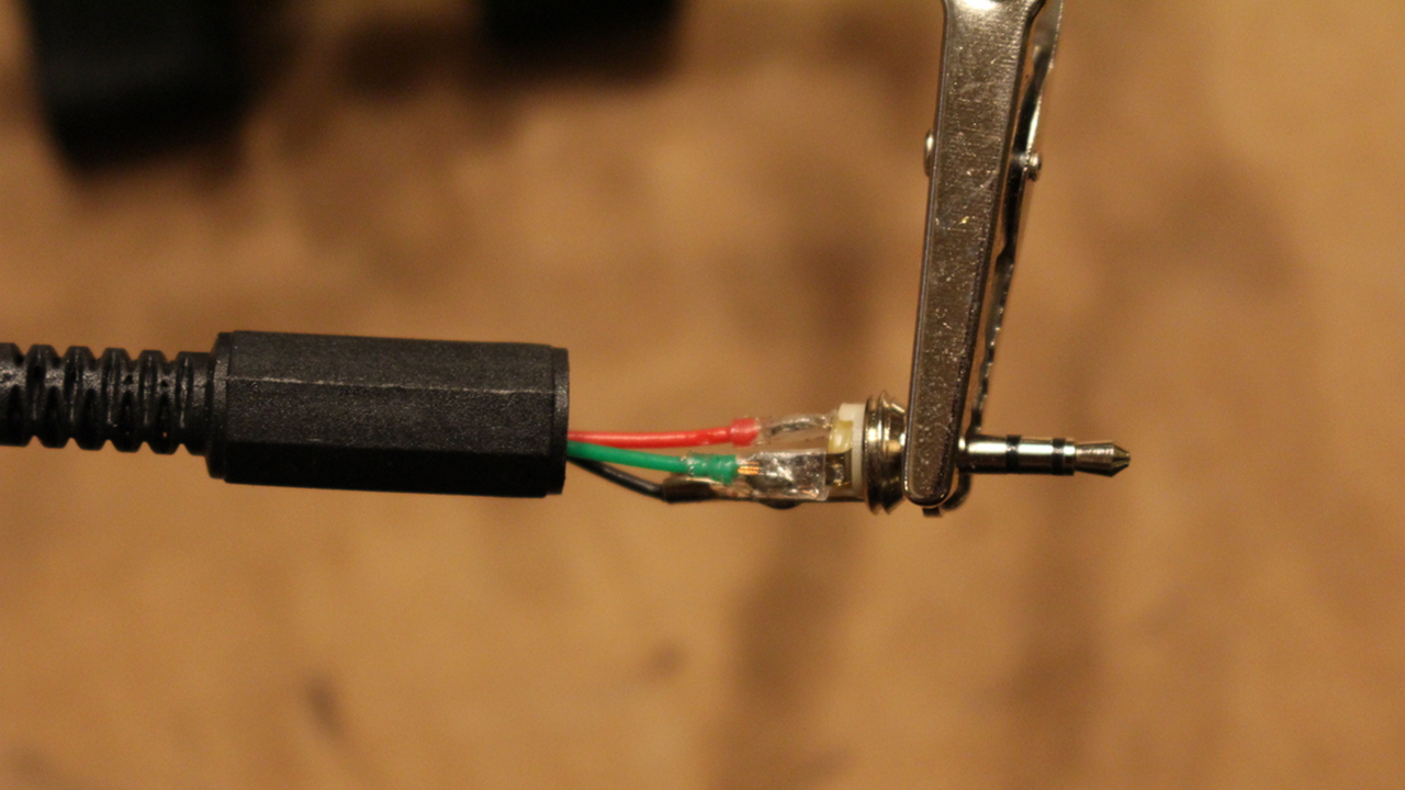 I do recommend that you start with soldering of the audio plug to the cable. This is the easiest part and can be completed quickly.
Take off the protective cap of the audio plug leaving the pins exposed. Pass the cable through the protective cap so that once finished, you can put the cap back on the audio plug.
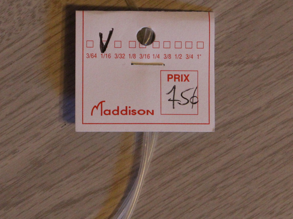
Cut 3 pieces of 1/8 inch (each) from the heat shrink tubing. Insert a piece of tubing over each wire that we are about to solder: black, red and green.
Locate the black wire of the cable. This is the ground wire. Skin a small amount of the cable (1/8 inch) and solder to the ground connector of the audio plug which is the longest pin.
Locate the red wire. This cable will trigger the shutter. Solder the wire to the left pin of the plug.
Solder the green wire (last) to the right pin of the plug. This will trigger the auto-focus of your camera.
Cut the yellow wire. You won’t need it.
Put the heat shrink tubing over each soldered section to protect the circuit.
If you have issues finding which pin are what, refer to the following image:
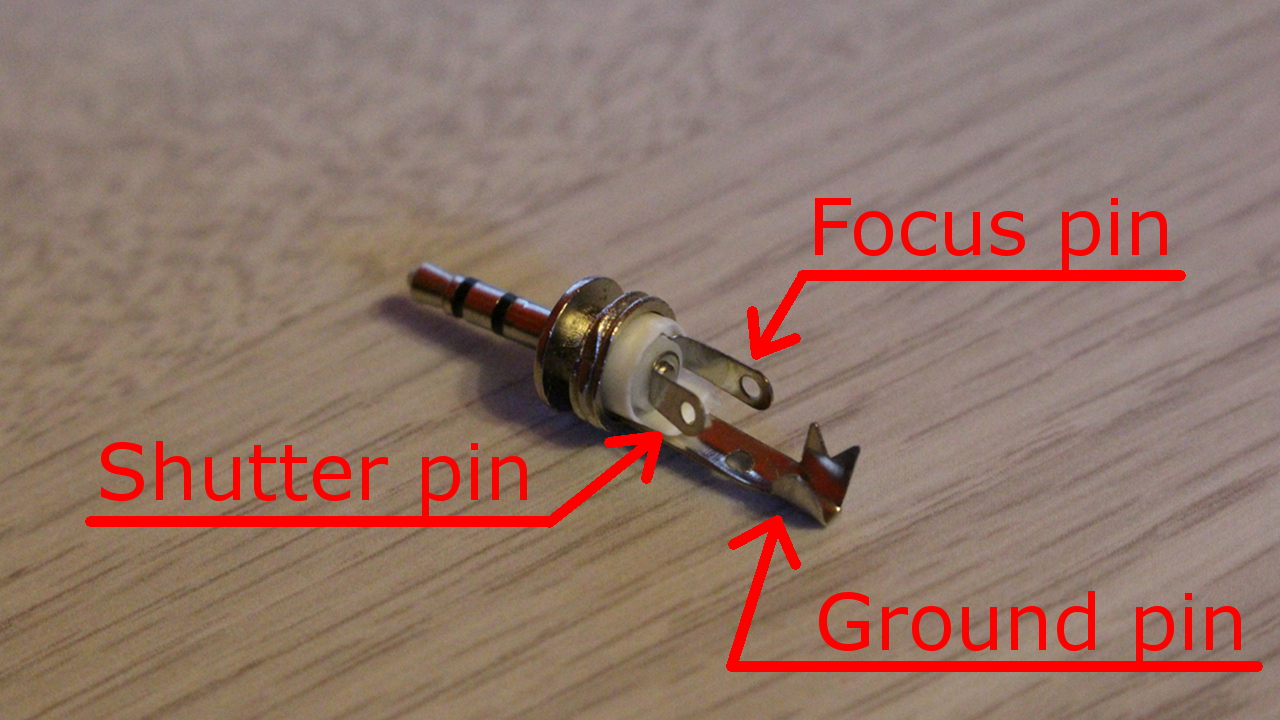
Audio plug 2.5 mm pins usage
Drilling
Next you have to drill two holes in the project box to insert the switches. Take your time to look for the best location for inserting your switches. I made my holes at a 90 degrees angle so that I could activate auto-focus with my index and activate the shutter with my thumb.
A third hole is also required at the bottom of the box to insert the cable.
If you project box is too fragile, you may have to drill many times the same hole using bigger and bigger drill bits. Another option is to use your soldering iron to melt holes in the plastic.
Wiring
Take your phone cable and insert the other end into the project box and tie a knot to prevent the wire from pulling on the switches solder joints. You can also put a small amount of hot glue on the knot inside the box for the same purpose.
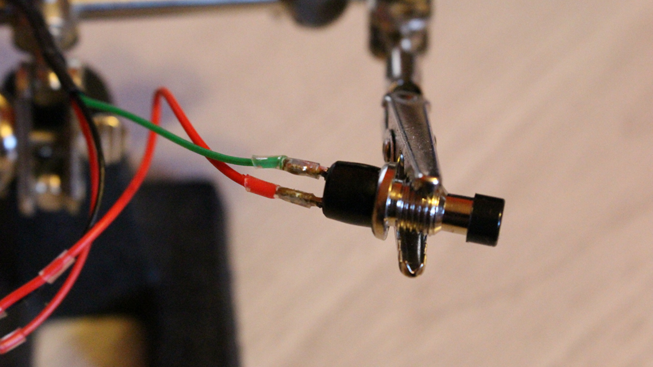
Soldering the switches
Remote trigger auto-focus button
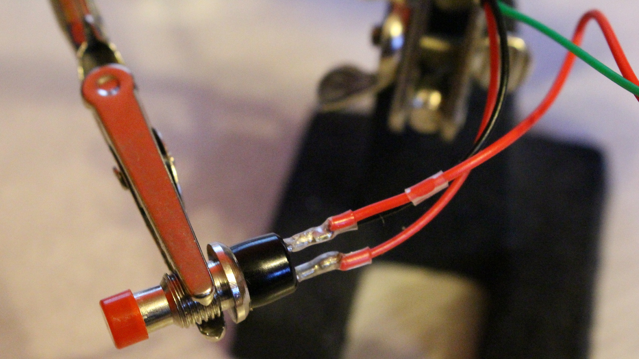
Remote trigger shutter button
In this section, you will solder the wires to the switches. The next set of instructions will assume that you want the red switch to trigger the shutter.
The ground wire (black) must be shared between the two switches. Take a short wire (preferably black) and solder one end to the black wire to make a Y shape. Solder each endings to a pin of each switch. The pins of the switch does not have a polarity which means that any pins can be used.
Take the red wire and solder the wire to the remaining pins of the red switch (shutter button). Do the same with the green wire and solder to the last pin of the black button (auto-focus button).
Please note that in the pictures above, I had to use a red wire to make the Y shape since I didn’t had any black wire.
Mounting
That should be obvious…
Final Result
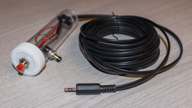
Here is the final result:

DIY Remote trigger shutter release cable for your Canon DSLR camera
Made anything differently?
I do not think that I would make anything differently. Everything is pretty much like the way I wanted.
Notes
none